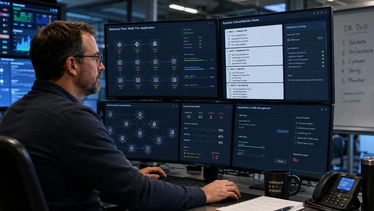
Envision a disaster-recovery test where the database, application, and web servers all boot successfully, yet the business service stays dark. Why? The new identity server never came up, and the database’s final consistency check was skipped. This mistake happens when we treat “infrastructure launch” as the goal. On August 28, 2026, AWS announced Elastic Disaster Recovery (DRS) recovery plans, a feature designed to orchestrate multi-server launches.
Recovery plans let you group servers into ordered steps. Each step launches its servers in parallel, and the plan waits for every participating job to reach a terminal state before advancing. A terminal state is only “instance up” or “failed to launch”; it does not prove end-to-end service health. In practice, every infrastructure step needs an application-level gate.
Think of recovery as a state machine that begins before a disaster: inventory ready → replication OK → plan initiated → infrastructure up → application validation → traffic cutover → business sign-off → cleanup. Each state has an owner, such as a system administrator, application owner, database administrator (DBA), network team, or executive, and clear exit criteria based on logs, test results, and metrics. After database servers launch, for example, the DBA team must confirm data consistency and open listeners before the next wave starts. We also track RTO (recovery time objective) and RPO (recovery point objective) for each state. The AWS Well-Architected Reliability Pillar emphasizes defining those objectives from business needs and testing the implementation. The simplified recovery-state model below assigns an owner and evidence to every stage.
Recovery State | Owner/Role | Evidence/Criteria |
Replication Ready | DR Engineering Lead | Up-to-date block-level replication, latest snapshot timestamp, replication lag metrics checked |
Recovery Plan Initiated (Drill) | Operations Lead | Recovery plan execution started, console logs showing “Started” |
Infrastructure Launch | Cloud/Ops Team | All EC2 instances running (status=Running), OS-level checks (network reachability/SSH) |
Application Validation | Application Teams | Tier-specific health checks (DB accepts queries, app responds to API, web returns HTTP 200) passed |
Traffic Cutover Ready | Network/IT Team | Load balancer or DNS records ready, connections successful to standby environment |
Business Sign-Off | Business Stakeholders | Formal go/no-go decision recorded (for example email or ticket) |
Recovery Complete / Cleanup | DR Engineering | All non-required resources terminated; RTO/RPO measured and documented |
Launching servers is not the same as recovering a service. AWS recovery plans establish infrastructure order, but application teams must add validation gates between steps. A plan can start the web tier as soon as the application tier reaches its terminal infrastructure state, even when the web tier cannot reach identity or database services. Treat each row in the model as a gate: collect the evidence, obtain the named owner’s approval, and only then advance.
This operating model sits inside broader resilience engineering. Refonte Learning’s cloud-native disaster recovery and resilience guide provides additional context on redundancy and failure testing, while this runbook stays focused on AWS DRS recovery-plan execution.
1. Recovery Plans Orchestrate Launches, Not Business Recovery
AWS recovery plans define when and in what order to launch servers, but they do not know whether the application works. The service launches every server in Step 1 in parallel, waits until the recovery jobs reach terminal status, and then advances to Step 2. “Finished” means that the recovery job succeeded or failed; it does not include application health.
Consider a three-step plan: databases → applications → web. AWS can start all database instances and wait for the launch jobs to finish. If a database instance boots without access to its disk-decryption key, the infrastructure can appear up while the database remains unusable. Without a custom validation gate, the plan may continue to the application and web tiers, producing a system that is running but broken.
Prevent that outcome by defining exit criteria for every recovery state. A server’s impact level controls what the plan does when recovery fails. Critical is the default: the step and execution fail, and remaining steps do not run. Optional records the server failure but allows the plan to continue. Use Optional only for components the application can start without, such as a reporting server, and keep dependencies Critical.
If a step contains only Optional servers and every one fails, the plan can still advance. Impact levels do not override pre-execution or step-start validation: a validation failure can stop the execution even when the affected server is Optional. Treat an early validation failure as a stop condition, correct the configuration, and retry or restart according to the runbook.
Finally, define the overall RTO and RPO goals with business owners. AWS Well-Architected guidance says those objectives should reflect business needs. Keep them visible while designing states and measurements. An e-commerce checkout service, for example, might have an illustrative target of recovery within 20 minutes and less than one minute of data loss. The recovery plan and evidence process should be designed around the approved targets, but only measured drills can show whether they are achieved.
2. Inventory Source Servers and Define the Recovery Unit
Every recovery plan starts with a detailed inventory. List each source server and classify it so you know what needs protection. Use a schema like this:
Application and Tier: Group servers by application and tier, for example Accounting-DB, Accounting-App, and E-Commerce-Web. Tier 1 may contain core databases, while a lower tier may contain logging or analytics services.
Criticality: Mark services as critical or optional. This classification drives step order and the impact setting assigned to each server.
Owner and Team: Identify the business owner and technical owner for every service, such as the database, application, and network teams. Escalate any ownership gap before a drill or incident.
Environment: Label production, development, test, and quality-assurance systems clearly. Only the systems required to recover the production service should enter the production recovery plan.
Operating System and Role: Record the operating system and server role, such as database, application, web, or directory service.
Recovery Unit: Identify groups of servers that must recover together. A database cluster, for example, may be managed as one recovery unit even when it contains several source servers.
RTO and RPO Targets: Record the approved recovery time objective and recovery point objective for each application or tier, using a clear unit such as minutes or seconds.
Dependencies: List every provider relationship, for example Web depends on App, while App depends on the database and corporate Active Directory.
Replication Status: Confirm that AWS DRS replication is enabled and healthy for every source server. Capture errors, lag, and the timestamp of the latest usable recovery point.
The inventory template below shows the minimum fields to retain:
Field | Description / Example |
Source Server Name | for example acct-db-01 |
Application/Tier | for example Accounting: Primary Database (Tier 1) |
Owner/Team | for example Finance IT / DBA Team |
Environment | for example Production |
OS / Data Role | for example RHEL Linux / OLTP DB (main accounting DB) |
Criticality (Tier) | for example Tier 1 (must meet RTO 10 min, RPO 15 sec) |
Recovery Group | for example DatabaseCluster1 |
Dependencies (IDs) | for example depends on auth-server and storage LUNs |
Replication Status | for example Active, last sync 5 sec ago, 200 KB/s lag |
Keep the inventory current. AWS DRS uses continuous block-level sync, which can provide recent recovery points when replication is healthy. Track agent connectivity, replication lag, and recovery-point freshness so a stale or disconnected server is visible before a drill. Group servers by application to define recovery units, for example Group 1 for Accounting databases, Group 2 for Accounting application servers, and Group 3 for e-commerce web servers.
Document RTO, RPO, and required evidence for every application and tier. During each drill, record elapsed recovery time and the observed data gap. AWS Well-Architected disaster-recovery guidance calls for objectives based on downtime and data-loss requirements, followed by testing against those objectives. The inventory should therefore identify where evidence will be collected, such as Amazon CloudWatch logs, validation output, or AWS DRS job history.
3. Build the Application Dependency Graph
Next, explicitly map every dependency. Think of your application as a graph: nodes are servers or services, edges are “needs” relationships. List hard dependencies (the application will break without these) and soft dependencies (optional enhancements). Include:
Application Dependencies: Application servers may depend on databases, while web servers may depend on the application tier.
Data and Consistency Dependencies: A reporting service may depend on a database snapshot or read replica, which in turn depends on the primary database reaching an accepted state.
Identity and Directory Dependencies: Record authentication servers, Active Directory, and Lightweight Directory Access Protocol (LDAP) directories. Centralized login is a hard dependency when users or services cannot authenticate without it.
Network and Connectivity Dependencies: Include the virtual private cloud (VPC), subnets, routes, private endpoints, firewalls, and access to managed services such as Amazon Relational Database Service (Amazon RDS).
External Services: Record software-as-a-service APIs, identity providers, payment gateways, and other external endpoints, including any recovery-specific callback, allowlist, or credential requirements.
DNS and Service-Discovery Dependencies: Record the hostnames, zones, resolvers, and service-discovery records that must point to the recovery environment.
Human Decisions: Record manual actions and approvals, such as running a schema migration, changing a route, or authorizing traffic cutover.
Represent the application as a diagram or dependency matrix. Check for cycles, such as Service A requiring Service B while Service B also requires Service A. Break the cycle with an explicit startup mode, temporary data source, queue, or manual control. Escalate any dependency without a named owner because an unowned dependency cannot be validated or approved during recovery.
For example, your dependency list might include:
WebFront → AppFront → Accounting-DB (hard)
AppFront → AuthService (hard)
Reporting → Accounting-DB (soft, not needed to start)
AnyServer → Corporate-DNS (hard for discovery)
AnyServer → KMS-CA (hard, decrypt keys)
System administrator → manual network change (human dependency, for example a routing update)
A hard dependency means the consumer cannot start or operate correctly without its provider, so the provider must recover first. An optional logging or reporting service can be assigned a lower impact level when the business service can start without it. Identity, external-service, and DNS dependencies may require dedicated runbook steps rather than another source-server launch.
By mapping dependencies before a drill, you can translate the graph into launch order: independent servers can share a wave, while dependent services wait for the provider tier. Refonte Learning’s cloud architecture trends and best practices guide offers broader context on distributed-system ownership and observability; this article applies those principles to recovery sequencing.
4. Translate Dependencies into Recovery Steps and Waves
Use Parallel Launches Only Where Dependencies Allow
AWS can launch multiple servers within one step, but use that parallelism only when the servers do not depend on one another. Two load-balanced web servers may launch together. Servers that share a single virtual Internet Protocol address, require leader election, or must register with a peer need additional sequencing or startup validation. The governing rule is simple: servers in the same plan step will launch in parallel, so peers belong together only when their relative launch order does not matter.
Define each recovery step, or wave, around one application tier or a set of independent servers. Every wave should specify:
Entry Criteria: State what must be true before the step starts, such as successful validation and approval of the previous wave.
Exit Criteria: State the infrastructure and application checks that must pass before promotion.
Timeout and Retry Policy: Define the maximum wait time, the number of allowed retries, and the point at which the incident commander must choose another action.
Impact Level: Assign Critical or Optional to every participating source server, based on whether the next wave or the business service depends on it.
Stop or Continue Policy: Define whether a server failure blocks the plan, permits a controlled continuation, or requires a manual decision.
Keep the documented plan limits in mind: a recovery plan can contain up to 100 source servers across a maximum of 20 steps. A plan cannot have more than one execution in a non-terminal state at the same time. Design recovery waves within those boundaries. The following example is illustrative:
Step (Wave) | Servers Included | Entry Condition | Exit (Validation) | Notes |
Step 1 (DB) | All Tier-1 Database servers | Plan start (or drill initiation) | DB up, listening, data consistent (sample query) | Timeout 20 min; Abort on fail |
Step 2 (App) | All Tier-1 Application servers | Step 1 exit OK | App up, app port open, can connect to DB | Can launch up to 10 in parallel |
Step 3 (Web) | All Web front-end servers | Step 2 exit OK | Web server returns 200 on homepage URL | Postpone load balancer attach until validation |
Step 4 (Auth/Other) | (If separate identity tier) | Step 2 exit OK | Auth service responds, certificates valid | Set to Optional if redundant |
Set the impact level deliberately in every wave. A database server that the application requires should normally be Critical. A reporting or analytics server that does not block service startup may be Optional. Remember that a validation failure at the start of execution can still stop the plan, even when the affected server is Optional. Preflight validation therefore belongs in the operating runbook, not only in the AWS configuration.
Parallelism must follow the dependency graph. Web and application servers might be technically independent at the host level, yet the web tier should still wait until application validation passes. Before placing servers in the same wave, confirm that none needs configuration, registration, data, identity, or network state supplied by another member of that wave.
5. Standardize Launch Settings, Networking, and Identity
Once the plan is defined, configure the AWS DRS launch settings for each source server. AWS creates those settings and an EC2 launch template when a source server is added, but you should verify and customize both before relying on them:
Instance Type: Select an instance type that can support the recovered workload. A default such as t3.medium may be suitable only for some systems, so compare compute, memory, storage, and licensing needs with the source specification and drill measurements.
Subnet and VPC: Pre-create the required recovery subnets, routes, and internet or private egress. Configure the launch template to use the intended virtual private cloud rather than relying on a default VPC that may not match the production network design.
Security Groups: Attach the correct security groups in the launch template. For example, allow the database port only from the application tier and the application port only from the web tier. Use separate, clearly tagged controls for drills so test systems cannot mix with production traffic.
IAM Instance Profile: When a server must retrieve secrets or access Amazon S3, assign an AWS Identity and Access Management (IAM) instance profile. Confirm that the required roles and policies exist in the target account and Region.
Network Endpoints: Confirm that the recovery subnets can reach required AWS PrivateLink endpoints and services such as AWS Systems Manager and AWS Secrets Manager. Create the necessary VPC endpoints and routes in the target Region before the drill.
Encryption Keys: Confirm that the AWS Key Management Service (AWS KMS) keys and permissions needed to decrypt replicated volumes are available in the recovery environment. Missing key access can leave an instance launched but its data unavailable.
Hostnames and IP Addresses: Decide whether the recovery environment needs preserved private IP addresses, fixed addresses, or stable hostnames. Reserve the address space and align the decision with DNS, certificates, and allowlists.
Launch Template Tags: Apply environment, exercise, application, owner, and cost-center tags to recovery instances and related resources. Consistent tags support isolation, cleanup, evidence collection, and cost reporting.
DRS Agent Health: Confirm that the AWS Replication Agent is connected and current on every source server. A disconnected source cannot provide the expected recovery point, even when its launch settings appear complete.
Configuration-Drift Management: Track launch-template and recovery-network changes outside the source operating system. Review the configuration after production changes and use AWS Config or another control to detect drift in security groups, IAM, routes, tags, and templates.
AWS documents defaults intended to simplify launch configuration, but networking, identity, sizing, licensing, and Region-specific dependencies still require verification. A recovery plan can contain up to 100 source servers, so larger applications need multiple plans or another documented orchestration boundary.
Standardize and test launch profiles before a disaster. Review the DRS launch settings and EC2 launch template for every source server, including subnet, instance type, licensing, storage, security groups, IAM, and tags. Keep development, test, and production networks separate so a drill cannot accidentally send or receive production traffic.
6. Define Recovery Points and Data-Consistency Checks
Now address data. AWS DRS continuously replicates block data from the source environment to AWS, supporting low recovery point objectives for crash-consistent recovery. AWS documentation also confirms that AWS Elastic Disaster Recovery replication is crash-consistent. In-flight memory writes may not be represented in the selected recovery point, so applications such as databases may need additional controls for application consistency. Plan how to obtain and validate a clean data state:
Point-in-Time Selection: After initial synchronization, DRS maintains recovery points. For each drill or recovery, choose the latest acceptable point or a point before a known corruption event. Record the selected Coordinated Universal Time (UTC) timestamp and recovery-point identifier.
Crash-Consistent versus Application-Consistent Data: Block replication captures on-disk state, but it does not flush application memory or operating-system caches. A database may therefore require a native checkpoint, write pause, backup, or other application-aware control before the selected point can be accepted as consistent.
Database Validation: After the database tier launches, run the database-specific integrity checks and sample queries defined by the DBA. Examples include SQL Server DBCC CHECKDB, PostgreSQL checksum verification, and controlled row-count or hash comparisons against expected values.
Replication-Lag Evidence: Record the recovery-point timestamp and DRS lag evidence before launch. Use the difference between the incident time and selected recovery point when calculating the observed RPO. Investigate any lag that exceeds the approved threshold.
Data-Owner Acceptance: Include the data steward or system owner in validation for critical data sets. A controlled transaction, such as creating and reading back a test invoice, can confirm business-level correctness beyond a storage or database process check.
Between waves, include explicit point-in-time (PIT) selection and consistency controls. The following sample is illustrative:
Data/Consistency Step | Purpose | Method / Check |
Select Recovery Point | Meet RPO target | Note snapshot timestamp, ensure replication lag = X sec |
Flush Database (if needed) | Ensure app-consistency | Issue DB checkpoint or dump; or pause app writes briefly |
Post-Recovery DB Query | Validate data integrity | Query key records / row counts; check for errors |
Verify Logins/Transactions | Confirm end-to-end data | Run a sample transaction (for example create and read back an item) |
Always log the chosen recovery point (UTC timestamp) and compare it to your RPO objective. For example, if disruption is at 10:00:00 and you recovered at 10:00:20, your RPO was 20 seconds. AWS literature cites RPOs of seconds and RTOs of minutes for well-tuned setups, but you should verify these in real drills, not rely on marketing. Maintain a simple record (spreadsheet or log) of each drill’s recovery point and achieved RPO/RTO for auditing.
For broader database context, Refonte Learning’s database administration performance and recovery guide discusses the operational balance among performance, security, backup, and recovery. In this runbook, database recovery remains one gated tier within the full application service.
7. Separate Drill, Recovery, Cutover, and Failback Procedures
Treat drills, live recoveries, cutover, and failback as separate phases with distinct owners:
Drill (Test Recovery): Conduct a scheduled rehearsal without directing production users to the recovery environment. The disaster-recovery lead coordinates the plan, records RTO and RPO evidence, captures lessons, and reports results to stakeholders.
Declared Disaster: A named executive, business-continuity authority, or delegated incident commander formally declares the disaster and authorizes production recovery. Document that authority for each application before an incident.
Recovery Launch: The infrastructure or cloud-operations team starts and monitors the recovery-plan execution. The operations lead records progress and escalates failed Critical servers or blocked steps through the incident process.
Data Validation and Cutover: After every tier passes its validation gates, the network and systems teams prepare Domain Name System (DNS), load balancer, or address changes. Production traffic moves only after the authorized go decision.
Business Sign-Off: The business or quality-assurance owner verifies the core workflow with recovered data. The service is not declared recovered until that owner records acceptance.
Failback: Once primary systems are repaired, you may need to fail back. The operations team must coordinate data replication or restoration, application validation, and traffic redirection to the primary environment. AWS provides a failback client to replicate data from recovery instances back to an on-premises source server, but DNS and load-balancer changes remain separate operational tasks. Define clear readiness criteria, such as a restored primary database seeded with current recovery-site data, before approving failback.
Cleanup and Closure: After a drill, stabilized recovery, or completed failback, the disaster-recovery team removes temporary resources, confirms termination, closes evidence gaps, and records corrective actions.
Organize these into a State-Transition Table with RACI-style owners and actions, for clarity:
Phase | Description | Owner/Actor | Action/Decision Required |
Drill/Test | Practice run (no real failover) | DR Team Lead | Execute plan; record metrics; report results |
Disaster Declared | Formal recovery authorization | Executive/CIO | Authorize plan execution; mobilize teams |
Recovery Launch | AWS recovery plan execution | Cloud/Ops Team | Monitor plan; escalate failures; fix issues |
Validation | Run application-level checks | App/QA Teams | Verify services; report pass/fail |
Traffic Cutover | Redirect production traffic | Network/IT Team | Update DNS/load balancer; verify connectivity |
Business Sign-off | Confirm business functions work | Business Stakeholders | Approve that service is restored |
Failback | (if applicable) reverse to primary | Operations Team | Sync data back; flip traffic; test primary |
Closure | Clean up and document | DR Team Lead | Terminate resources; document lessons |
Assign decision rights explicitly. For example, only a named executive can declare “Disaster” and thus authorize the recovery plan run; only the business leader can sign off “Service OK” after cutover. For drills, the DR lead can terminate the exercise if needed. Listing these in your recovery plan or runbook ensures everyone knows their authority and responsibilities at each step.
AWS DRS executes the plan steps automatically, but it does not enforce these high-level transitions. Pause the workflow or run manual controls between waves when application validation or approval is required. In a drill, for example, keep production DNS unchanged until every tier is validated. Record each human approval at the transition so the evidence trail shows why the recovery was allowed to advance.
8. Add Application Validation Between Infrastructure Steps
Do not treat a running instance as a recovered tier. After each wave, execute the application-specific checks and block promotion until all required checks pass:
Operating-System and Node Health: Confirm that the operating system has booted, initialization has completed, and approved administrative access such as Secure Shell (SSH) or Windows Remote Management (WinRM) works.
Service Health: Verify that the required processes are running and listening, such as a database engine, Java service, Node.js process, or web server.
Port and Endpoint Checks: Test every required port and health endpoint from the same network path the dependent tier will use.
Dependency Tests: From the application tier, test database and identity connectivity. From the web tier, call an application endpoint through the intended recovery network path.
Synthetic Transaction: Run a realistic, controlled transaction, such as signing in, retrieving a known test record, or placing a non-production test order. This often exposes failures that a process or port check misses.
Data Integrity: Query the database or application to confirm that expected records and relationships are present.
Business-Process Simulation: Execute the scripted end-to-end workflow that represents the service’s critical business function.
Security and Secrets Check: Confirm that certificates, keys, secrets, and external credentials are available and that the recovered instance can retrieve them through the intended identity and network controls.
Structure these checks as promotion gates. After Step 1 launches the database tier, the DBA team runs the approved validation and records the result before Step 2 starts. AWS recovery plans do not perform these application tests for you, so the runbook must provide the manual approval or adjacent automation that holds the next wave.
For observability, integrate the normal monitoring stack. A Nagios or Prometheus check, a synthetic user-interface test, or an application-performance alert can provide the signal for a gate. Assign a correlation identifier to the recovery exercise so logs and alerts can be tied to the same event. These checks are automated smoke tests; Refonte Learning’s DevOps trends and career strategies guide provides broader context on monitoring, automation, and incident response.
When a validation fails, stop promotion and troubleshoot. Hold or cancel the next action according to the runbook, correct the dependency, and repeat the failed validation. Resume only when the required owner records a pass. In the worked exercise below, the team pauses after a missing secret and later after an identity failure before continuing.
9. Control DNS, Load Balancers, Secrets, and External Dependencies
Traffic control is frequently the final hidden dependency. A healthy recovery stack remains unavailable when DNS, load balancers, certificates, secrets, or external allowlists still reference the failed environment. Control each traffic-redirection element explicitly:
DNS TTLs and Failover: Set an approved time to live (TTL) for critical records before an incident. Use isolated drill names so a test cannot change production DNS, and document the exact record, health-check, and rollback procedure for cutover.
Load-Balancer Targets: Do not register or enable recovery targets until application validation has passed. When using Elastic Load Balancing, document target-group registration, health-check status, session behavior, and the rollback action.
Certificates: Confirm that the required Transport Layer Security (TLS) certificates and private keys are available in the recovery Region. AWS Certificate Manager (ACM) certificates are Regional, while imported or application-managed certificates require their own recovery procedure.
API and SaaS Keys: Replicate or recreate the approved application programming interface (API) keys and software-as-a-service credentials in the recovery account and Region. Validate retrieval from AWS Secrets Manager or AWS Systems Manager Parameter Store.
Network Allowlists and Blocklists: Update partner, administrative, and upstream allowlists with recovery addresses. At the same time, block unintended paths that could let the former primary database or application accept writes.
Prevent Split-Brain: Define one authoritative write location. In an active-passive design, fence or isolate the former primary before enabling writes in the recovery environment.
External Dependencies: Validate identity providers, payment gateways, webhooks, callback URLs, managed services, and SaaS integrations from the recovery network and identity context.
Treat traffic routing as a controlled state transition, not an automatic consequence of healthy instances. Before cutover, verify Amazon Route 53 records, load-balancer targets, certificates, secrets, external dependencies, and split-brain protections. A rollback procedure must restore the prior traffic state without enabling two writers.
Apply the same discipline used in cybersecurity monitoring and response: verify intended access, detect unintended paths, and confirm that only the recovery environment can receive production traffic before cutover.
10. Observe Plan Progress and Diagnose Partial Failure
During a drill or recovery, monitor infrastructure launch, operating-system startup, application validation, and traffic state separately. Use AWS service events together with host and application telemetry, and define how the team handles partial failure:
Logs and Events: Capture AWS DRS job status and relevant Amazon EventBridge events, plus Windows Event Logs, Linux system logs, and application logs. Apply the exercise correlation identifier to tickets, evidence, and resource tags.
Metrics: Monitor replication lag and throughput, instance CPU, memory, disk, and application health. A stalled launch, unusual resource profile, or missing heartbeat should trigger investigation before the timeout expires.
Stuck or Failed Plan: When a step does not reach terminal status, check Amazon EC2 quotas, capacity, launch-template errors, networking, storage, encryption, and operating-system startup. Follow the documented timeout and stop-or-continue decision instead of improvising during the incident.
Partial Success: An Optional server may fail while the plan continues, but the failure still belongs in the incident record and corrective-action backlog. A failed Critical server blocks promotion until the issue is corrected and the affected recovery action is rerun.
Manual Intervention: Define who may cancel, retry, or restart an execution, what evidence must be preserved first, and whether already launched resources may be reused. The runbook should state the safe restart boundary for every wave.
Correlation Identifiers: Assign a unique run identifier to every drill or declared disaster and use it in logs, tickets, approvals, validation output, and cost tags.
Alerting: Configure alerts for failed executions, unhealthy instances, replication degradation, and missed validation deadlines. Drills may be actively observed, but the same alerts must work during an out-of-hours production incident.
Partial-Plan Evidence: Record the plan, step, source server, job status, error, intervention, and rerun result. Preserve exported or captured AWS job details with the application-validation evidence.
Operational Context: Treat recovery drills, synthetic tests, and controlled failure exercises as normal reliability work. Any unresolved Critical step or failed promotion gate should receive the same operational attention as an outage.
By observing closely, you can diagnose issues. For example, maybe you find the plan reports “finished” but web servers aren’t actually responding; that means your validation (Section 8) caught it. Or you see replication lag increase; perhaps the network is saturated. Use these insights to improve the plan.
11. Clean Up Drill Resources and Control Recovery Cost
After a drill or a completed failback, shut down resources that are no longer required. AWS Elastic Disaster Recovery pricing includes a per-source-server service charge, while EC2 instances, EBS volumes, NAT gateways, load balancers, snapshots, and other resources generate their normal AWS charges. A forgotten drill instance or orphaned volume therefore remains a budget and governance issue. Implement the following cleanup guardrails:
Cleanup Manifest: List every resource that may be created or changed, including EC2 instances, Amazon EBS volumes, network interfaces, Elastic IP addresses, load balancers, snapshots, security groups, route entries, and temporary gateways. State whether each item is retained, reverted, or deleted.
Owners and Deadlines: Assign a cleanup owner and deadline. An illustrative drill policy may require temporary resources to be removed within 24 hours, while a live recovery retains resources until the business and failback owners authorize removal.
Termination Verification: Export the resource inventory before and after cleanup, then query the exercise tags to prove that no active resource remains outside the approved retention list.
Orphan Detection: Detect unattached EBS volumes, unused Elastic IP addresses, network interfaces, load balancers, snapshots, and other resources that can continue to generate cost after instances are terminated.
Snapshots: Define which recovery snapshots and evidence artifacts must be retained, for how long, and who authorizes deletion. Storage charges continue while retained snapshots remain.
Budget Alerts: Configure an AWS Budget alert for the disaster-recovery account and notify the cost owner when drill spending crosses the approved threshold. The service fee is billed per actively replicating source server, while recovery instances, storage, networking, and related services are charged according to their applicable AWS prices. Track the DRS service fee plus Amazon EC2, Amazon EBS, networking, and other drill resources in the exercise budget.
Cost Tags: Apply a consistent exercise, application, owner, and cost-center tag set. Use AWS Cost Explorer or the organization’s cost-management process to reconcile the drill manifest with billed resources.
Automation: Automate safe cleanup where possible, but protect resources that support an active incident or approved evidence-retention period. Require notification and an explicit exception path before an automated termination deadline.
Post-Test Report: Include cleanup completion, retained resources, exceptions, and observed cost in the drill report.
Cleanup discipline is part of disaster-recovery governance. Terminating instances is not enough: volumes, addresses, snapshots, load balancers, and network changes must also be reconciled. The completed manifest proves that the drill or recovery closed cleanly and did not leave unowned resources or ambiguous traffic paths.
12. Capture Audit Evidence and Measure RTO/RPO
Every drill or recovery should produce a timestamped evidence package for each state transition. Capture at least:
Initiation Time: Record the Coordinated Universal Time (UTC) at which the drill started or the disaster was declared, along with the selected recovery point.
Step Durations: Record the start, infrastructure-terminal, validation-pass, and approval times for every wave.
Validation Results: Preserve the command output, monitoring evidence, synthetic-test result, and named owner decision for every gate.
Failures and Actions: Record each failure, diagnosis, intervention, rerun, and outcome.
End Time: Record traffic cutover, business verification, and formal sign-off separately.
RTO Calculation: Calculate the observed recovery time objective as cutover completion time minus disaster declaration time. Compare it with the approved target RTO.
Achieved RPO: Calculate the data gap between the incident time and the selected, accepted recovery point. For example, a 09:58 recovery point for a 10:00 incident produces a two-minute observed RPO.
Resource Use and Cost: Reconcile launched and retained resources with the cleanup manifest and cost report.
Approvals: Preserve the disaster declaration, promotion decisions, traffic go or no-go, business sign-off, failback authorization, and closure approval.
Deviation Analysis: Compare each planned gate and objective with the observed result, including any missed RTO, RPO, timeout, or cleanup deadline.
Corrective Actions: Assign every gap an owner, due date, priority, and verification method for the next drill.
A Recovery Log Template could be a table with columns like:
Item | Planned | Achieved | Responsible | Evidence/Notes |
Recovery Point (time) | 09:59 | 09:58 | DR Team | Snapshot ID xyz (DB flushed at 09:58) |
Step 1 (DB) Start | 10:00 | 10:00 | Cloud Ops | Initiated at 10:00 via console |
Step 1 (DB) End | 10:10 | 10:12 | DB Team | DB validation passed (query output) |
Step 2 (App) End | 10:20 | 10:19 | App Team | App responded (health check passed) |
Step 3 (Web) End | 10:25 | 10:24 | App Team | Web UI loaded homepage |
Traffic Cutover | 10:30 | 10:27 | Network | Route 53 updated; connectivity check passed |
Total RTO | 15 min | 27 min | (calculated) | Fell short of target; DNS delay contributed |
Data Consistency (RPO) | 0 min | 2 min | DR Team | Last backup 09:58; outage 10:00 |
Compare planned, observed, and accepted results. Highlight missed criteria and preserve the business owner’s decision to accept, reject, or conditionally accept the outcome. The evidence package should show what happened, not merely that the AWS plan reached a terminal status.
The AWS Well-Architected guidance to test disaster recovery implementation to validate the implementation is the governing principle: a configured plan is not evidence. Measured results show whether the application reached the accepted state within the observed recovery time and data-loss window. Repeated drill records also reveal trends, such as a growing RTO or a validation that fails in every exercise.
13. Work Through a Three-Tier Recovery Exercise
Consider this illustrative three-tier application: Database → Application → Web, with a separate identity service used by the application tier. Its recovery waves are:
Wave 1 (Database Tier): Two database servers with synchronous replication. Entry: recovery execution is authorized. Exit: both databases are running, accepting SQL connections, and pass the defined consistency checks.
Wave 2 (Application and Identity Tier): Two application servers and one identity server. Entry: Wave 1 passes validation. Exit: the applications can query the database and authenticate through the identity service.
Wave 3 (Web Tier): Three web servers. Entry: Wave 2 passes validation. Exit: the web tier serves the required HTTP endpoint and passes the synthetic transaction.
Illustrative execution timeline:
09:50: The drill starts without production traffic. The team selects the 09:49 recovery point, producing an initial one-minute data gap for measurement.
09:52: Wave 1 launches. Both database EC2 instances reach the running state and their ports open, but the database validation fails because the application account secret was not seeded in AWS Secrets Manager for the recovery environment.
09:55: The authorized engineer creates the missing secret, records the change, and reruns the database validation.
09:58: Both databases pass validation. A controlled query returns the expected row count, so Wave 1 exits successfully.
10:00: Wave 2 launches. The application instances start, but the recovery identity service cannot complete its directory dependency. Application logs show login failures, so promotion stops even though the EC2 launches succeeded.
10:03: The identity owner corrects the dependency and restarts the identity service. The team does not begin Wave 3 until authentication is retested.
10:06: Both application servers pass database-connectivity and authentication checks. Wave 2 exits successfully.
10:08: Wave 3 launches. The web servers boot and start their web-service processes.
10:10: The web endpoint returns HTTP 200, but the first browser login fails because session state is not ready. The team holds the traffic decision, reruns the synthetic login, and records a pass.
10:12: Wave 3 passes its exit criteria. All infrastructure tiers are running and application validation is complete, but production traffic remains unchanged.
10:13: The authorized network owner updates Amazon Route 53 to direct the public name to the recovery web tier. A final controlled order succeeds, and the business owner signs off at 10:15.
Measured Result: The illustrative recovery time is 25 minutes, and the selected recovery point is one minute behind the drill start. These values are exercise results, not service guarantees.
Outcome: Every EC2 launch succeeded, but database-secret and identity checks blocked promotion. The team corrected one missing secret, reran the affected validation, delayed the traffic decision until login passed, and captured the intervention. Infrastructure success did not become service recovery until application and business gates were complete.
Assume the illustrative target RTO was 20 minutes. The observed 25-minute result is a five-minute miss caused by the validation pauses. The corrective-action record should address secret replication, identity recovery order, and the synthetic-login readiness check before the next drill.
14. Execute the 90-Day Adoption Plan
Adopt AWS DRS recovery plans in controlled application waves. An illustrative 90-day rollout is:
Days 1–30: Inventory and Planning: Build the source-server inventory and dependency graphs, approve RTO and RPO targets, draft recovery waves and launch settings, complete a tabletop review, and run one pilot drill for a lower-risk application. Assign the disaster-recovery lead, application owner, database owner, identity owner, network owner, and business approver.
Days 31–60: Expand and Refine: Onboard the next application group, refine validation scripts and synthetic transactions, update the runbook from drill evidence, enforce cost tags and cleanup controls, and establish the agreed drill calendar.
Days 61–90: Scale and Improve: Drill mission-critical applications in scheduled waves, cross-train operators, automate repeatable validation and cleanup tasks, compare observed RTO and RPO with approved targets, close high-priority gaps, and present the evidence package to leadership.
Treat adoption as both a technical and organizational change. Use the project to strengthen networking, infrastructure as code, monitoring, cloud management, automation, and backup and recovery. Refonte Learning’s system administration engineering guide provides broader skills context without replacing the application-specific AWS DRS runbook developed here.
By day 90, an illustrative exit criterion is that every Tier 1 application has an owned inventory, approved dependency graph, configured recovery plan, completed drill, documented RTO and RPO result, cleanup evidence, and a corrective-action backlog. Monthly drills should be scheduled only where that cadence matches the workload’s risk and governance requirements.
In practice, the first actions are to inventory the source servers, map dependencies, and sketch the recovery waves. AWS DRS recovery plans automate launch sequencing, but they do not replace application validation or governance. Gate every step with health checks, and assign decision rights for disaster declaration, cutover, rollback, failback, and closure. Only measured drills can show whether the service meets its accepted recovery objectives.
Readers who want a structured foundation in backup and recovery, cloud systems, networking, troubleshooting, virtualization, security, and command-line administration can review the Refonte Learning System Administration Program. The live program page lists a six-month period at 10–12 hours per week and states that successful participants receive a Training Certificate and a Certificate of Internship. It does not explicitly state that AWS DRS recovery plans are covered, so verify tool-specific coverage before enrollment.